VTP Introduction & Modes
 The invention of VLANs was very much welcomed by all engineers and administrators, allowing them to extend, redesign and segment their existing network with minimal costs, while at the same time making it more secure, faster and reliable!
If you're responsible for a network of up to 4-6 switches that include a few VLANs, then you'll surely agree that it's usually a low overhead to administer them and periodically make changes - most engineers can live with that:)
Ask now an engineer who's in charge of a medium to a large scale network and you will definately not receive the same answer, simply because these small changes can quickly become a nightmare and if you add the possibility of human error, then the result could be network outages and possibly downtime.
Welcome To Virtual Trunk Protocol (VTP)
VTP, a Cisco proprietary protocol, was designed by Cisco with the network engineer and administrator in mind, reducing the administration overhead and the possibility of error as described above in any switched network environment.
When a new VLAN is created and configured on a switch without the VTP protocol enabled, this must be manually replicated to all switches on the network so they are all aware of the newly created VLAN. This means that the administrator must configure each switch separately, a task that requires a lot of time and adds a considerable amount of overhead depending on the size of the network.
The configuration of a VLAN includes the VLAN number, name and a few more parameters which will be analysed further on. This information is then stored on each switch's NVRAM and any VLAN changes made to any switch must again be replicated manually on all switches.
If the idea of manually updating all switches within your network doesn't scare you because your network is small, then imagine updating more than 15-20 switches a few times per week, so your network can respond to your organisation's needs....have we got you thinking now? :)
With the VTP protocol configured and operating, you can forget about running around making sure you have updated all switches as you only need to make the changes on the nominated VTP server switch(es) on your network. This will also ensure these changes are magically propagated to all other switches regardless of where they are.
Introducing The VTP Modes
The VTP protocol is a fairly complex protocol, but easy to understand and implement once you get to know it. Currently, 3 different versions of the protocol exist, that is, version 1, 2 (adds support for Token Ring networks) and 3, with the first version being used in most networks.
Despite the variety of versions, it also operates in 3 different modes: Server, client and transparent mode, giving us maximum flexibility on how changes in the network effect the rest of our switches. To help keep things simple and in order to avoid confusion, we will work with the first version of the VTP protocol - VTP v1, covering more than 90% of networks.
Below you'll find the 3 modes the VTP protocol can operate on any switch throughout the network:
- VTP Server mode
- VTP Client mode
- VTP Transparent mode
Each mode has been designed to cover specific network setups and needs, as we are about to see, but for now, we need to understand the purpose of each mode and the following network diagram will help us do exactly that.
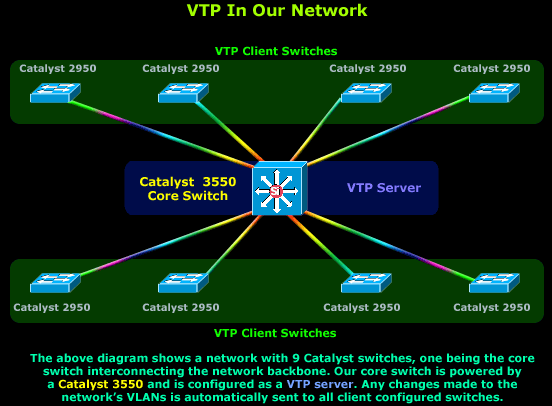
A typical setup involves at least one switch configured as a VTP Server, and multiple switches configured as VTP Clients. The logic behind this setup is that all information regarding VLANs is stored only on the VTP Server switch from which all clients are updated. Any change in the VLAN database will trigger an update from the VTP Server towards all VTP clients so they can update their database.
Lastly, be informed that these VTP updates will only traverse Trunk links. This means that you must ensure that all switches connect to the network backbone via Trunk links, otherwise no VTP updates will reach the rest of the switches.
Let's now take a closer look at what each VTP mode does and where it can be used.
VTP Server Mode
By default all switches are configured as VTP Servers when first powered on. All VLAN information such as VLAN number and VLAN name is stored locally, on a separate NVRAM memory which is where the device's startup-config is stored. This happens only when the switch is in VTP Server mode.
For small networks with a limited number of switches and VLANs, storing all VLAN information on every switch is usually not a problem, but as the network expands and VLANs increase in number, it becomes a problem and a decision must be made to select a few powerful switches as the VTP Servers while configuring all other switches to VTP Client mode.
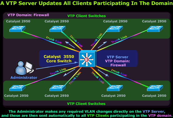
The diagram above shows a Cisco Catalyst 3550 selected to take the role of the network's VTP Server since it is the most powerful switch. All other Catalyst switches have been configured as VTP Clients, obtaining all VLAN information and updates from the 3550 VTP Server.
The method and frequency by which these updates occur is covered in much detail on the pages that follow, so we won't get into any more detail at this point. However, for those who noticed, there is a new concept introduced in the above diagram that we haven't spoken about: The VTP Domain.
The VTP Domain - VLAN Management Domain
The VTP Domain, also known as the VLAN Management Domain, is a VTP parameter configured on every switch connected to the network and used to define the switches that will participate in any changes or updates made in the specified VTP domain.
Naturally, the core switch (VTP Server) and all other switches participate in the same domain, e.g firewall, so when the VTP Server advertises new VLAN information for the VTP firewall domain, only clients (switches) configured with the same VTP Domain parameter will accept and process these changes, the rest will simply ignore them.
Lastly, some people tend to relate the VTP Domain with the Internet Domain name space, however, this is completely incorrect. Even though the acronym 'DNS' contains the word 'Domain', it is not related in any way with the VTP Domain. Here (in VTP land), the word 'Domain' is simply used to describe a logical area in which certain hosts (switches) belong to or participate in, and are affected by any changes made within it.
We should also note that all Cisco switches default to VTP Server mode but will not transmit any VLAN information to the network until a VTP Domain is set on the switch.
At this point we are only referencing the VTP Domain concept as this is also analyzed in greater depth further on, so let's continue with the VTP modes!
VTP Client Mode
In Client Mode, a switch will accept and store in its RAM all VLAN information received from the VTP Server, however, this information is also saved in NVRAM, so if the switch is powered off, it won't loose its VLAN information.
The VTP Client behaves like a VTP Server, but you are unable to create, modify or delete VLAN's on it.
In most networks, the clients connect directly to the VTP Server as shown in our previous diagram. If, for any reason, two clients are cascaded together, then the information will propagate downwards via the available Trunk links, ensuring it reaches all switches:
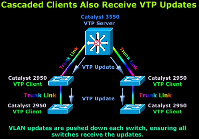
The diagram shows a 3550 Catalyst switch configured as a VTP Server and 4 Catalyst 2950 switches configured as VTP Clients and cascaded below our 3550. When the VTP Server sends a VTP update, this will travel through all trunk links (ISL, 802.1q, 802.10 and ATM LANE), as shown in the diagram.
The advertised information will firstly reach the two Catalyst 2950 switches directly connected to the 3550 and will then travel to the cascaded switches below and through the trunk links. If the link between the cascaded 2950's was not a trunk link but an access link, then the 2nd set of switches would not receive and VTP updates:
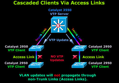
As you can see, the VTP updates will happlily arrive at the first catalyst switches but stop there as there are no trunk links between them and the 2950's below them. It is very important you keep this in mind when designing a network or making changes to the existing one.
VTP Transparent Mode
The VTP Transparent mode is something between a VTP Server and a VTP Client but does not participate in the VTP Domain.
In Transparent mode, you are able to create, modify and delete VLANs on the local switch, without affecting any other switches regardless of the mode they might be in. Most importantly, if the transparently configured switch receives an advertisement containing VLAN information, it will ignore it but at the same time forward it out its trunk ports to any other switches it might be connected to.
Note: A Transparent VTP switch will act as a VTP relay (forward all VTP information it receives, out its trunk ports) only when VTP version 2 is used in the network. With VTP version 1, the transparent switch will simply ignore and discard any VTP messages received from the rest of the network.
Lastly, all switches configured to operate in Transparent mode save their configuration in their NVRAM (just like all the previous two modes) but not to advertise any VLAN information of its own, even though it will happily forward any VTP information received from the rest of the network.
This important functionality allows transparently configured switches to be placed anywhere within the network, without any implications to the rest of the network because as mentioned, they act as a repeater for any VLAN information received:
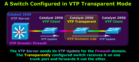
Our 3550 Catalyst here is configured as a VTP Server for the domain labelled "Firewall". In addition, we have two switches configured in VTP Client mode, obtaining their VLAN information from the 3550 VTP Server, but between these two VTP Clients, we have placed another switch configured to run in VTP Transparent mode.
Our Transparent switch has been configured with the domain called "Lab", and as such, the switch will forward all incoming VTP updates belonging to the "Firewall" domain out its other trunk link, without processing the information. At the same time, it won't advertise its own VLAN information to its neighbouring switches.
Closing, the VTP Transparent mode is not often used in live networks, but is well worth mentioning and learning about.
Summary
This page introduced a few new and very important concepts. The VTP Protocol is considered to be the heart of VLANs in large scale networks as it completely makes the administration point of view easy and transparent for every switch on your network.
We briefly spoke about the three different modes offered by the VTP protocol: Server, Client and Transparent mode. To assist in providing a quick summary, the table below shows the main characteristics for each mode:
| VTP Mode | Description |
|---|---|
| VTP Server |
The default mode for all switches supporting VTP. You can create, modify, and delete VLANs and VTP servers advertise their VLAN configurations to other switches in the same VTP domain and synchronize their VLAN configurations with other switches based on advertisements received over trunk |
| VTP Client | Behaves like a VTP server, but you cannot create, change, or delete VLANs on a VTP client. VLAN configurations are saved in NVRAM. |
| VTP Transparent |
Does not advertise its VLAN configuration and does not synchronize its VLAN configuration based on received advertisements. However, they will forward VTP advertisements as they are received from other switches. You can create, modify, and delete VLANs on a switch in VTP transparent mode. VLAN configurations are saved in NVRAM, but they are not advertised to other switches. |
All switches by default are configured as VTP Servers but without a domain. At this point we need to select the 'Core' switch (usually the most powerful) and configure it as a VTP Server, while reconfiguring all the rest to Client mode. Also, VTP Updates sent by the Server will only propagate through trunk links configured for ISL, IEEE 802.1q, 802.10 or LANE encapsulation.
You should be aware that all VTP Messages are sent through what we call the "Management VLAN". This specially created VLAN is usually the first one in the network - VLAN 1 - and by rule is never used by anyone else other than the switches themselves.
The creation of a Management VLAN ensures all switches have their own network to communicate between each other without any disruptions.
The next article will analyse the VTP Protocol structure, messages and updates. This will provide a deep understanding on how VTP works and what information it's messages contain. For those out there keen on configuring a switch for VTP, it's covered towards the end of the VLAN topic as shown on the VLAN Introduction page.
Your IP address:
3.17.145.236
Wi-Fi Key Generator
Follow Firewall.cx
Cisco Password Crack
Decrypt Cisco Type-7 Passwords on the fly!


