VLAN InterSwitch Link (ISL) Protocol Analysis
 Deciding whether to use ISL or IEEE 802.1q to power your trunk links can be quite confusing if you cannot identify the advantages and disadvantages of each protocol within your network.
This article will cover the ISL protocol in great detail, providing an insight to its secrets and capabilities which you probably were unaware of. In turn, this will also help you understand the existence of certain limitations the protocol has, but most importantly allow you to decide if ISL is the tagging process you require within your network.
InterSwitch Link (ISL)
ISL is Cisco's propriety tagging method and supported only on Cisco's equipment through Fast & Gigabit Ethernet links. The size of an ISL frame can be expected to start from 94 bytes and increase up to 1548 bytes due to the overhead (additional fields) the protocol places within the frame it is tagging.
These fields and their length are also shown on the diagram below:
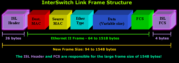
We will be focusing on the two purple coloured 3D blocks, the ISL header and ISL Frame Check Sequence (FCS) respectively. The rest of the Ethernet frame shown is a standard Ethernet II frame as we know it. If you need more information, visit our Ethernet II page.
The ISL Header
The ISL header is 26 byte field containing all the VLAN information required (as one would expect), to allow a frame traverse over a Trunk Link and find its way to its destination.
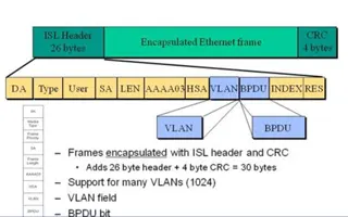
Here is a closer look at the header and all the fields it contains:

You can see that the ISL header is made out of quite a few fields, perhaps a lot more than what you might have expected, but this shouldn't alarm you as only a handful of these fields are important. As usual, we will start from the left field and work our way to the far right side of the header. First up...... the DA field:
Destination Address (DA) Field
The 'DA' field is a 40 bit destination address field that contains a multicast address usually set to "0x01-00-0C-00-00" or "0x03-00-0C-00-00". This address is used to signal to the receiver that the packet is in ISL format.
Type Field
The 'Type' field is 4 bits long and helps identify the encapsulated original frame. Depending on the frame type, the ISL 'Type' field can take 4 possible values as outlined in the table below:
| Type Value |
Encapsulated Frame |
|---|---|
| 0000 | Ethernet |
| 0001 | Token-Ring |
| 0010 | FDDI |
| 0011 | ATM |
The 4 bits of space assigned to the 'Type Value' field allow a maximum of 2^4=16 different values. Since all combinations are not used, there is plenty of room for future encapsulations that might be developed.

User Defined Field
The 'User' field occupying 4 bits serves as an extension to the previous 'Type' field and is mostly used when the original encapsulated frame is an Ethernet II type frame. When this happens, the first two bits of the 'User' field act as a prioritisation mechanism, allowing the frames to find their way to the destination much faster.
Currently, there are 4 different priorities available, as shown in the table below:
| Type Value |
Frame Priority |
|---|---|
| XX00 | Normal Priority |
| XX01 | Priority 1 |
| XX10 | Priority 2 |
| XX11 | Highest Priority |
We should also note that the use of priorities is optional and not required.

Source Address (SA) Field
The 'SA' field is the source MAC address of the switch port transmitting the frame. This field is -as expected- 48 bits long. The receiving device can choose to ignore this field. It is worth noting that while the Destination Address field located at the beginning of the header contains a multicast MAC Address, the Source MAC address field we are looking at here contains the MAC address of the sending device - usually a switch.
Length Field
The 'Length' field is 16 bits long and contains the whole ISL frame's length minus the DA, Type, User, SA, LEN and FCS fields. If you're good at mathematics, you can easily calculate the total length of the excluded fields, which is 18 bytes. With this in mind, a quick way to find this field's value is to take the total frame size and subtract 18 bytes :)
Length fields are used in frames to help the receiving end identify where specific portions of the frame exist within the frame received.

AAAA03 (SNAP) Field
The SNAP field is a 24 bit long field with a value of "0xAAAA03".
High bits Source Address (HSA) Field
The 'HSA' field is a 24 bit value. This field represents the upper three bytes of the SA field (the manufacturers ID portion) and must contain the value "0x00-00-0C". Since the SA field is 48 bits long or 6 bytes, the upper 3 bytes of the SA field would translate to 24 bits, hence the length of the HSA field.

VLAN - Destination Virtual LAN ID Field
The VLAN field is the Virtual LAN ID of the frame. This is perhaps the most important field of all as our frame moves between trunk links because it allows all trunk links to identify the VLAN this frame belongs to. The VLAN ID field is 15 bits long and often referred to as the "color" of the frame.
Without this field, there would be no way of identifying which VLAN the frame transitting a trunk link belongs to.
Bridge Protocol Data Unit (BPDU) & Cisco Discovery Protocol (CDP) Indicator
The 'BPDU' field is only 1 bit long but very important as it is set for all BPDU packets encapsulated by the ISL frame. For those unaware, BPDU's are used by the Spanning Tree Protocol (STP) to shut down redundant links and avoid network loops. This field is also used for CDP and Virtual Trunk Protocol (VTP) frames that are encapsulated.
Index Field
The Index field is a 16 bit value and indicates the port index of the source of the packet as it exits the switch. It is used for diagnostic purposes only and may be set to any value by other devices.
RES Field - Reserved for Token Ring and Fiber Distributed Data Interface (FDDI)
The RES field is a 16 bit value and used when Token Ring or FDDI packets are encapsulated with an ISL frame. In the case of Token Ring frames, the Access Control (AC) and Frame Control (FC) fields are placed here whereas in the case of FDDI, the FC field is placed in the Least Significant Byte (LSB) of this field (as in a FC of 0x12 would have a RES field of 0x0012). For Ethernet packets, the RES field should be set to all zeros.
Frame Check Sequence (ISL FCS)
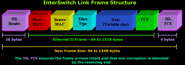
Coming to the end of the ISL protocol analysis, we met the FCS field which consists of four bytes. The FCS contains a 32-bit CRC value, which is created by the sending MAC (switch) and is recalculated by the receiving MAC (switch) to check for corrupt frames. In an Ethernet II frame, the FCS is generated using the Destination MAC, Source MAC, Ethertype, and Data fields while ISL's FCS is calculated based on the entire ISL frame and added to the end of it.
Summary
This article analysed all fields of the ISL header and FCS. The next page deals with the popular IEEE 802.1q, an alternative to Cisco's ISL tagging protocol.
Wi-Fi Key Generator
Follow Firewall.cx
Cisco Password Crack
Decrypt Cisco Type-7 Passwords on the fly!


