OSPF - Part 2: How OSPF Protocol Works & Basic Concepts: OSPF Neighbor, Topology & Routing Table, OSPF Areas & Router Roles, Theory & Overview
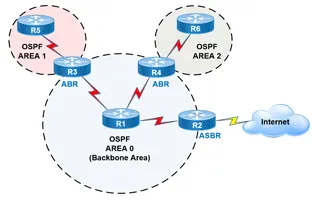 This article covers basic OSPF concepts and operation. We explain how OSPF works, how OSPF tables are built on an OSPF-enabled router and their purpose (Neighbour Table, Topology Table, Routing Table), OSPF areas and their importance. Next we cover OSPF Link State Packet types used to exchange data between OSPF routers: Link State Advertisement (LSA), Link State Database (LSDB), Link State Request (LSR), Link State Update (LSU) and Link State Acknowledgment (LSAcK).
Finally, we take a look at the OSPF roles: Area Boarder Router (ABR), Autonomous System Boundary Router (ASBR), Designated Router (DR), Backup DR and more.
Below is a complete list of articles covering our OSPF Series:
What Is OSPF & How Does It Work?
OSPF is a Link State protocol that’s considered may be the most famous protocol among the Interior Gateway Protocol (IGP) family, developed in the mid 1980’s by the OSPF working group of the IETF.
When configured, OSPF will listen to neighbors and gather all link state data available to build a topology map of all available paths in its network and then save the information in its topology database, also known as its Link-State Database (LSDB). Using the information from its topology database. From the information gathered, it will calculate the best shortest path to each reachable subnet/network using an algorithm called Shortest Path First (SFP) that was developed by the computer scientist Edsger W. Dijkstra in 1956. OSPF will then construct three tables to store the following information:
- Neighbor Table: Contains all discovered OSPF neighbors with whom routing information will be interchanged
- Topology Table: Contains the entire road map of the network with all available OSPF routers and calculated best and alternative paths.
- Routing Table: Contain the current working best paths that will be used to forward data traffic between neighbors.
Understanding OSPF Areas
OSPF offers a very distinguishable feature named: Routing Areas. It means dividing routers inside a single autonomous system running OSPF, into areas where each area consists of a group of connected routers.
The idea of dividing the OSPF network into areas is to simplify administration and optimize available resources. Resource optimization is especially important for large enterprise networks with a plethora of network and links. Having many routers exchange the link state database could flood the network and reduce its efficiency – this was the need that led to the creation of concept Areas.
Areas are a logical collection of routers that carry the same Area ID or number inside of an OSPF network, the OSPF network itself can contain multiple areas, the first and main Area is called the backbone area “Area 0”, all other areas must connect to Area 0 as shown in the diagram below:
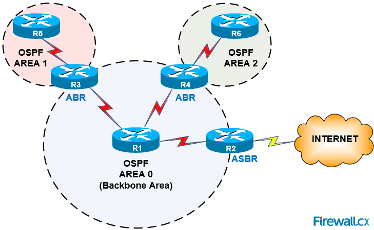
Figure 1. OSPF Areas, Area 0 (Backbone Area), ABR and ASBR OSPF routers
All routers within the same Area have the same topology table -Link State Database- but different routing table as OSPF calculates different best paths for each router depending on its location within the network topology while they will all share the same Link State topology.
The goal of having an Area is to localize the network as follow:
- The Area boundaries will give the opportunity of using summarization, as it’s not possible to summarize network prefixes in normal link state protocols because routers are supposed to have the same map topology of the entire network coincide in all neighbors.
- Area boundaries will also help preventing fault containment by suppressing updates that take place when a change occurs in the network causing a flood of updates between routers. This also happens to be a weakness of link state protocols: When connecting large sized networks it is very difficult to avoid link state database floods.
With Area boundaries, updates are kept only inside the same area, while other areas remain completely unaware of the update.
OSPF Link State Packet Types
OSPF routers generate packets of information that are exchaged with neighboring routers. These packets are designed for several purposes such as forming neighbor relations between routers, calculating cost and best path for a specific route and more.
The following is a list of the most frequently used OSPF packets:
Link State Advertisement (LSA): The primary mean of communication between OSPF routers, it's the packet that carries all fundamental information about the topology and is flooded between areas to perform different functions, there are 11 types of LSA packets that will be covred in great depth in future OSPF articles here on Firewall.cx
Link State DataBase (LSDB): LSDB packet contains all updated link-state information exchanged among the network, and all routers within the same area have identical LSDB, and when two routers form new neighbor adjacency, they sync their LSDB to be fully adjacent.
Link State Request (LSR): Once neighbor adjacency is formed and LSDB is exchanged, neighbor routers may locate a missing LSDB information, they then send a request packet to claim the missing piece, neighbors receive this packet and respond with LSU.
Link State Update (LSU): A response packet sends a specific piece of LSDB information requested by an OSPF neighbor via LSR packet.
Link State Acknowledgment (LSAcK): The router that sends the LSR packet confirms receiving the LSU from neighbor by sending a confirmation packet acknowledging receiving the requested LSUs.
Working Inside Of A Single Area
Working inside of an Area is hierarchically organized among routers that share this area and are categorized as:
Area Boarder Routers (ABR):
Routers located on the borders of each Area connect to more than one OSPF area, are called ABR Routers. ABR Routers are responsible for summarizing IP addresses of each area and suppressing updates among areas to prevent fault containment.
Autonomous System Boundary Router (ASBR):
An ASBR is a router that has interfaces connected to one or more OSPF areas, similarly as the ABR, however the difference with an ASBR is that it also connects to other routing systems such as BGP, EIGRP, Internet and others. An ASBR router normally advertises routes from other routing systems into the OSPF area to which it belongs.
Designated Router (DR):
A Designated Router is elected by the routers on multi-access segments (e.g Local Area Network), based on its priority (Router ID, priority). The DR router performs special functions such as generating Link State Advertisements (LSAs) and exchanging information with all other routers in the same Area. Every router in the same Area will create an adjacency with the DR and BDR (analysed below).
The DR sends updates to all Area routers using the Multicast address 224.0.0.5. All OSPF routers except the DR use Multicast address 224.0.0.6 to send Link State Update (LSU) and Link State Advertisements (LSAs) packets to the DR.
Backup Designated Router (BDR):
The BDR is a router that becomes the DR should the existing DR fail. The BDR has the second highest priority (the DR having the highest priority) in the OSPF network. When the BDR becomes a DR, a new election is made to find a new BDR.
This article introduced the OSPF protocol and examined how OSPF works. We covered important OSPF concepts such as OSPF areas, OSPF Neighbour Table, Topology Table and Routing Table, plus OSPF Link State packet types (LSA, LSDB, LSR, LSU & LSAcK). To complete our introduction, we analysed the OSPF roles Area Boarder Router (ABR), Autonomous System Boundary Router (ASBR), Designated Router (DR), Backup DR.
Wi-Fi Key Generator
Follow Firewall.cx
Cisco Password Crack
Decrypt Cisco Type-7 Passwords on the fly!


