Palo Alto Firewall Configuration Options. Tap Mode, Virtual Wire, Layer 2 & Layer 3 Deployment modes
Our previous article explained how Palo Alto Firewalls make use of Security Zones to process and enforce security policies. This article will explain the different configuration options for physical Ethernet and logical interfaces available on the Palo Alto Firewall.
It’s easy to mix and match the interface types and deployment options in real world deployments and this seems to be the strongest selling point of Palo Alto Networks Next-Generation Firewalls. Network segmentation becomes easier due to the flexibility offered by a single pair of Palo Alto appliances.
Below is a list of the configuration options available for Ethernet (physical) interfaces:
- Tap Mode
- Virtual Wire
- Layer 2
- Layer 3
- Aggregate Interfaces
- HA
Following are the Logical interface options available:
- VLAN
- Loopback
- Tunnel
- Decrypt Mirror
The various interface types offered by Palo Alto Networks Next-Generation Firewalls provide flexible deployment options.
Tap Mode Deployment Option
TAP Mode deployment allows passive monitoring of the traffic flow across a network by using the SPAN feature (also known as mirroring).
A typical deployment would involve the configuration of SPAN on Cisco Catalyst switches where the destination SPAN port is the switch port to which our Palo Alto Firewall connects, as shown in the diagram below:

Figure 1. Palo Alto Next Generation Firewall deployed in TAP mode
The advantage of this deployment model is that it allows organizations to closely monitor traffic to their servers or network without requiring any changes to the network infrastructure.
During the configuration of SPAN it is important to ensure the correct SPAN source and SPAN Destination ports are configured while also enabling Tap mode at the Firewall.
Tap mode offers visibility of application, user and content, however, we must be mindful that the firewall is unable to control the traffic as no security rules can be applied in this mode. Tap mode simply offers visibility in the ACC tab of the dashboard. The catch here is to ensure that the tap interface is assigned to a security zone.
Virtual Wire (V-Wire) Deployment Option
Virtual Wire, also know as V-Wire, deployment options use Virtual Wire interfaces. The great thing about V-Wire deployment is that the firewall can be inserted into an existing topology without requiring any changes to the existing network topology.
The V-Wire deployment options overcome the limitations of TAP mode deployment, as engineers are able to monitor and control traffic traversing the link. A Virtual Wire interface supports App-ID, User-ID, Content-ID, NAT and decryption.

Figure 2. Palo Alto Next Generation Firewall deployed in V-Wire mode
Layer 2 Deployment Option
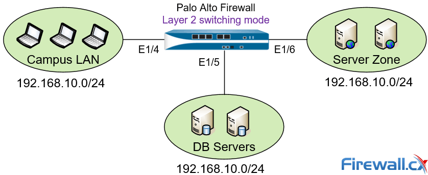
Palo Alto Networks Next Generation Firewall can also be deployed in Layer 2 mode. In this mode switching is performed between two or more network segments as shown in the diagram below:

Figure 3. Palo Alto Next Generation Firewall deployed in Layer 2 mode
In Layer 2 deployment mode the firewall is configured to perform switching between two or more network segments. Traffic traversing the firewall is examined, as per policies, providing increased security and visibility within the internal network.
In this mode the firewall interfaces are capable of supporting Access or Trunk Links (802.1Q trunking) and do not participate in the Spanning Tree topology. Any BPDUs received on the firewall interfaces are directly forwarded to the neighboring Layer 2 switch without being processed. Routing traffic between VLAN networks or other networks can be achieved via a default Gateway which is usually a Layer 3 switch supporting InterVLAN routing, a Firewall security appliance, or even Router-on-a-Stick design.
Layer 3 Deployment Option
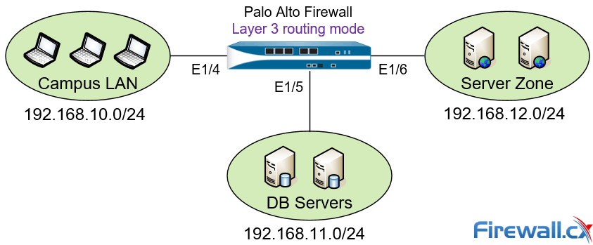
Layer 3 deployment mode is a popular deployment setup. In this mode the firewall routes traffic between multiple interfaces, each of which is configured with an IP address and security zone. The Firewall interfaces can also be configured to obtain their IP address via a DHCP server and can be used to manage the security appliance.

Figure 4 – Palo Alto Next Generation Firewall deployed in Layer 3 mode
The diagram above shows a typical Layer 3 deployment setup where the Firewall routes and controls traffic between three different IP networks. Similar to other setup methods, all traffic traversing the Firewall is examined and allowed or blocked according to the security policies configured.
Summary
In this article we examined a few of the different deployment modes available for Palo Alto firewalls. We talked about Tap mode, Virtual Wire mode, Layer 2 and Layer 3 deployment modes. Each deployment method is used to satisfy different security requirements and allows flexible configuration options. Visit our Palo Alto Firewalls Section for more in-depth technical articles.
Your IP address:
14.52.234.100
Wi-Fi Key Generator
Follow Firewall.cx
Cisco Password Crack
Decrypt Cisco Type-7 Passwords on the fly!


