Windows 2012 Server NIC Teaming – Load Balancing/Failover (LBFO) and Cisco Catalyst EtherChannel LACP Configuration & Verification
NIC Teaming, also known as Windows Load Balancing or Failover (LBFO), is an extremely useful feature supported by Windows Server 2012 that allows the aggregation of multiple network interface cards to one or more virtual network adapters. This enables us to combine the bandwidth of every physical network card into the virtual network adapter, creating a single large network connection from the server to the network. Apart from the increased bandwidth, NIC Teaming offers additional advantages such as: Load balancing, redundant links to our network and failover capabilities.
Windows Hyper-V is also capable of taking advantage of NIC Teaming, which further increases the reliability of our virtualization infrastructure and the bandwidth available to our VMs.
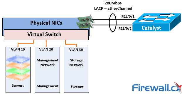
Figure 1. Windows 2012 Server – Hyper-V NIC Teaming with Cisco Catalyst Switch
There are two basic NIC Teaming configurations: switch-independent teaming & switch-dependent teaming. Let’s take a look at each configuration and its advantages.
Switch-Independent Teaming
Switch-independent teaming offers the advantage of not requiring the switch to participate in the NIC Teaming process. Network cards from the server can connect to different switches within our network.
Switch-independent teaming is preferred when bandwidth isn’t an issue and we are mostly interested in creating a fault tolerant connection by placing a team member into standby mode so that when one network adapter or link fails, the standby network adapter automatically takes over. When a failed network adapter returns to its normal operating mode, the standby member will return to its standby status.
Switch-dependent teaming requires the switch to participate in the teaming process, during which Windows Server 2012 negotiates with the switch creating one virtual link that aggregates all physical network adapters’ bandwidth. For example, a server with four 1Gbps network cards can be configured to create a single 4Gbps connection to the network.
Switch-dependent teaming supports two different modes: Generic or Static Teaming (IEEE 802.3ad) and Link Aggregation Control Protocol Teaming (IEEE 802.1ax, LACP). LACP is the default mode in which Windows NIC Teaming always operates.
Load Balancing Mode - Load Distribution Algorithms
Load distribution algorithms are used to distribute outbound traffic amongst all available physical links, avoiding bottlenecks while at the same time utilizing all links. When configuring NIC Teaming in Windows Server 2012, we are required to select the required Load Balancing Mode that makes use of one of the following load distribution algorithms:
Hyper-V Switch Port: Used primarily when configuring NIC Teaming within a Hyper-V virtualized environment. When Virtual Machine Queues (VMQs) are used a queue can be placed on the specific network adapter where the traffic is expected to arrive thus providing greater flexibility in virtual environments.
Address Hashing: This algorithm creates a hash based on one of the characteristics listed below and then assigns it to available network adapters to efficiently load balance traffic:
- Source and Destination TCP ports plus Source and Destination IP addresses
- Source and Destination IP addresses only
- Source and Destination MAC addresses only
- Distributes outgoing traffic based on a hash of the TCP Ports and IP addresses with real-time rebalancing allowing flows to move backward and forward between networks adapters that are part of the same group.
- Inbound traffic is distributed similar to the Hyper-V port algorithm
Dynamic: The Dynamic algorithm combines the best aspects of the two previous algorithms to create an effective load balancing mechanism. Here’s what it does:
The Dynamic algorithm is the preferred Load Balancing Mode for Windows 2012 and the one we are covering in this article.
Click here for more teachnical articles covering Windows Server
Configuring NIC Teaming in Windows Server 2012
In this example, we’ll be teaming two 100Mbps network adapters on our server. Both network adapters are connected to the same switch and configured with an IP address within the same subnet 192.168.10.0/24.
To begin, open Server Manager and locate the NIC Teaming section under Local Server:
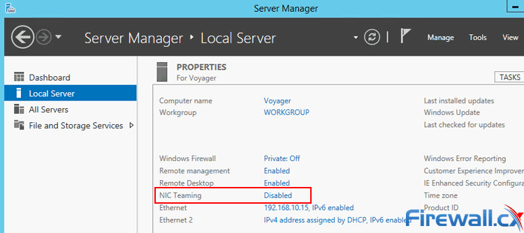
Figure 2. Locating NIC Teaming section in Server Manager Windows 2012 Server
The lower right section of the NIC Teaming window displays the available network adapters that can be assigned to a new team. In our case these are two 100Mbps Ethernet adapters.
From the TEAM area, select Tasks and then New Team from the dropdown menu to create a new NIC Team:
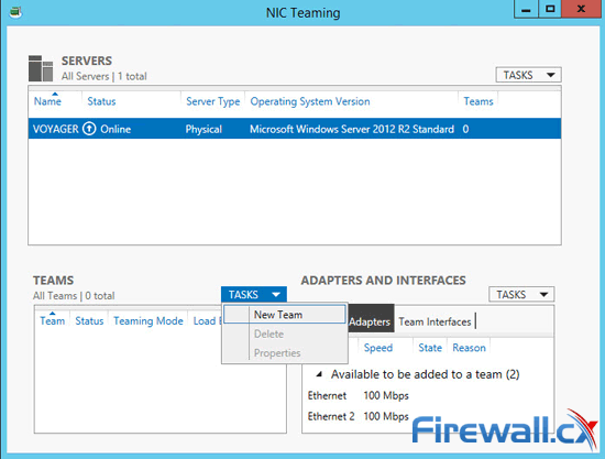 Figure 3. Creating a new NIC Team in Windows Server 2012
At the NIC Teaming window select the adapters to be part of the new NIC Team. Ensure Teaming mode is set to the desired mode (LACP in our case) and Load balancing mode is set to Dynamic. The Standby Adapter option will be available when more than two network adapters are available for teaming. Optionally we can give the new NIC Team a unique name or leave it as is.
Finally, we can select the default VLAN under the Primary Team Interface option (not shown below). When ready, click on OK to save the configuration and create the NIC Team:
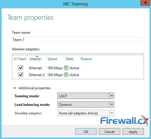 Figure 4. Configuring Teaming Mode, Load Balancing Mode and NIC Team members
Notice how the State of each network adapter is reported as Active – this indicates the adapter is correctly functioning as a member of the NIC Team.
When the new NIC Team window disappears we are brought back to the NIC Teaming window where Windows Server 2012 reports the NIC Teams currently configured, speed, status, Teaming Mode and Load Balancing mode:
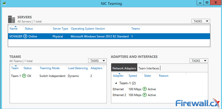 Figure 5. Viewing NIC Teams, their status, speed, Teaming mode, Load balancing mode and more
As mentioned earlier, NIC Teaming creates a virtual adapter that combines the speed of all network adapters that are part of the NIC Team. As we can see below, Windows Server has created a 200Mbps network adapter named Team-1:
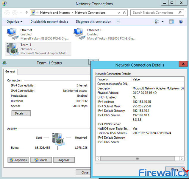 Figure 6. The newly created NIC Team Adapter in Windows 2012 Server
We should note that the MAC address used by the virtual adapter will usually be the MAC address from either physical network adapters.
Free Virtualization Backup with Award Winning Altaro Backup - Free Download Now!
Cisco Catalyst Switch Configuration
Depending on the type of NIC Teaming selected, the switch attached to the server might need to be configured. Cisco Catalyst switches fully support NIC Teaming and other types of link aggregation technologies through the use of EtherChannel. Cisco Catalyst provides support of the Link Aggregation Control Protocol (LACP) which also happens to be the default aggregation protocol when configuring EtherChannel.
More Information on Cisco Switches and configuration articles can be found in our dedicated Cisco Switches section
Create the Etherchannel interface by dedicating an equal number of switch ports to that of the physical network adapters participating in the NIC Teaming. In our example, we’ve got two network adapters so we’ll be using two switch ports.
Configure both switch ports to be part of Channel-Group 1 and set it to active mode. The Port-Channel interface will be configured in Trunk mode for our example:
Note: First create the Port-Channel interface and assign the physical interfaces to it using the channel-group 1 mode active command. After that, any commands entered under the Port-Channel interface will automatically be replicated to all port members (FastEthernet 1/0/1 & 1/0/2 in our example).
In case VLAN Trunking support is required, do not forget to use the switchport mode trunk command to enable trunking and then switchport trunk native vlan X to configure the native VLAN for the EtherChannel, replacing X with the necessary vlan number.
Additional Information: Configure VLANs and InterVLAN Routing on Cisco Catalyst switches
At this point, we are able to connect our server to the network. The show interface port-channel 1 command will provide a plethora of information about our Port-Channel, including bandwidth, interface members and other useful information:
The show Etherchannel 1 summary command provides additional information, including the aggregation protocol used, port members, their status and more:
This article covered Windows Server NIC Teaming and explained the different type of NIC Teaming, protocols involved, load & balancing distribution algorithms, configuration of Windows 2012 Server plus configuration of Cisco Catalyst switch configuration. To read more on Cisco switches, make sure you visit our Cisco Technical Knowledgebase which contains technical articles on Cisco switches, routers, firewalls and IP Telephony.
Your IP address:
3.21.158.143
Wi-Fi Key Generator
Follow Firewall.cx
Cisco Password Crack
Decrypt Cisco Type-7 Passwords on the fly!


