The Complete Cisco Nexus vPC Guide. Features & Advantages, Design Guidelines, Configuration, Failure Scenarios, Troubleshooting, VSS vs vPC
Cisco virtual Port Channel (vPC) is a virtualization technology, launched in 2009, which allows links that are physically connected to two different Cisco Nexus Series devices to appear as a single port channel to a third endpoint. The endpoint can be a switch, server, router or any other device such as Firewall or Load Balancers that support the link aggregation technology (EtherChannel).
To correctly design and configure vPC one must have sound knowledge of the vPC architecture components (vPC Domain, vPC Peer, vPC Peer-Link, vPC Peer Keepalive Link, vPC Member Port, vPC Orphan Port etc) but also follow the recommended design guidelines for the vPC Peer Keepalive Link and vPC Peer-Link. Furthermore, understanding vPC failure scenarios such as vPC Peer-Link failure, vPC Peer Keepalive Link failure, vPC Peer Switch failure, vPC Dual Active or Split Brain failure will help plan ahead to minimise network service disruption in the event of a link or device failure.
All the above including verifying & troubleshooting vPC operation are covered extensively in this article making it the most comprehensive and complete Cisco Nexus vPC guide.
The diagram below clearly illustrates the differences in both logical and physical topology between a non-vPC deployment and a vPC deployment:
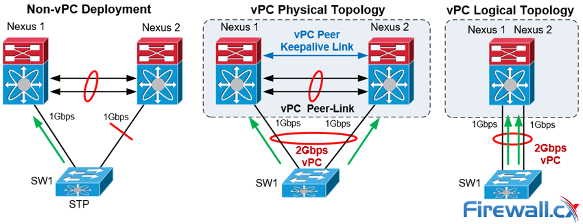
vPC Deployment Concept
The Cisco Nexus vPC technology has been widely deployed and in particular by almost 95% of Cisco Data Centers based on information provided by the Cisco Live Berlin 2016. In addition, virtual Port Channel was introduced in NX-OS version 4.1(4) and is included in the base NX-OS software license. This technology is supported on the Nexus 9000, 7000, 5000 and 3000 Series.
Let's take a look at the vPC topics covered:
- vPC Feature Overview & Guidelines
- vPC Architecture Components – vPC Peer, Peer-Link, Peer Keepalive Link, Domain, Member Port, Orphan Port and more
- Virtual Port Channel (vPC - Nexus) vs Virtual Switching System (VSS - Catalyst)
- vPC Peer Keepalive Link Design Guidelines
- vPC Peer-Link Design Guidelines
- vPC Failure Scenario: vPC Peer-Link Failure
- vPC Failure Scenario: vPC Peer Keepalive Link Failure
- vPC Failure Scenario: vPC Peer Switch Failure
- vPC Failure Scenario: vPC Dual Active / Split Brain Failure
- Nexus vPC Configuration & Troubleshooting Guide
- Verify Operation and Troubleshoot the Status of the vPC
- vPC Quiz
- Summary
We must point out that basic knowledge of the Cisco NX-OS is recommended for this article. You can also refer to our Introduction to Nexus Family – Nexus OS vs Catalyst IOS for an introduction study on the Nexus Series switches family. Finally, a Quiz is included at the last section and we are waiting for your comments and answers!
Additional related articles:
vPC Feature Overview & Guidelines
The Nexus 9000, 7000, 5000 and 3000 series switches take port-channel functionality to the next level by enabling links connected to different devices to aggregate into a single, logical link. The peer switches run a control protocol that synchronizes the state of the port channel and maintains it. In particular, the vPC belongs to the Multichassis EtherChannel (MEC) family of technology and provides the following main technical benefits:
- Eliminates Spanning Tree Protocol (STP) blocked ports
- Uses all available uplink bandwidth
- Allows dual-homed servers (dual uplinks) to operate in active-active mode
- Provides fast convergence upon link or device failure
- Offers dual active/active default gateways for servers
- Maintains independent control planes
- Simplifies Network Design
The following general guidelines and recommendations should be taken into account when deploying vPC technology at a Cisco Nexus Data Center:
- The same type of Cisco Nexus switches must be used for vPC pairing. It is not possible to configure vPC on a pair of switches consisting of a Nexus 7000 series and a Nexus 5000 series switch. vPC is not possible between a Nexus 5000 and Nexus 5500 switches.
- The vPC peers must run the same NX-OS version except during the non-disruptive upgrade, that is, In-Service Software Upgrade (ISSU).
- The vPC Peer-Link must consist of at least two 10G Ethernet ports in dedicated mode. Utilizing Ethernet ports from two different modules will improve the availability and redundancy should a module fail. Finally the use of 40G or 100G interfaces for vPC links will increase the bandwidth of the vPC Peer-Link.
- vPC keepalive link must be separate from the vPC Peer-Link.
- vPC can be configured in multiple VDCs, but the configuration is entirely independent. In particular, each VDC for the Nexus 7000 Series switches requires its own vPC peer and keepalive links and cannot be shared among the VDCs.
- The maximum number of switches in a vPC domain is two.
- The maximum number of vPC peers per switch or VDC is one.
- When Static routing from a device to vPC peer switches with next hop, FHRP virtual IP is supported.
- Dynamic routing adjacency from vPC peer switches to any Layer3 device connected on a vPC is not supported. It is recommended that routing adjacencies are established on separate routed links.
- vPC member ports must be on the same line card type e.g. M2 type cards at each end.
vPC Architecture Components – vPC Peer, Peer-Link, Keepalive Link, Domain, Member Port, Orphan Port & Member
vPC architecture consists of the following components:
vPC Peer
This is the adjacent device, which is connected via the vPC Peer-link. A vPC setup consists of two Nexus devices in a pair. One acts as the Primary and the other as a Secondary, which allows other devices to connect to the two chassis using Multi-Channel Ethernet (MEC).
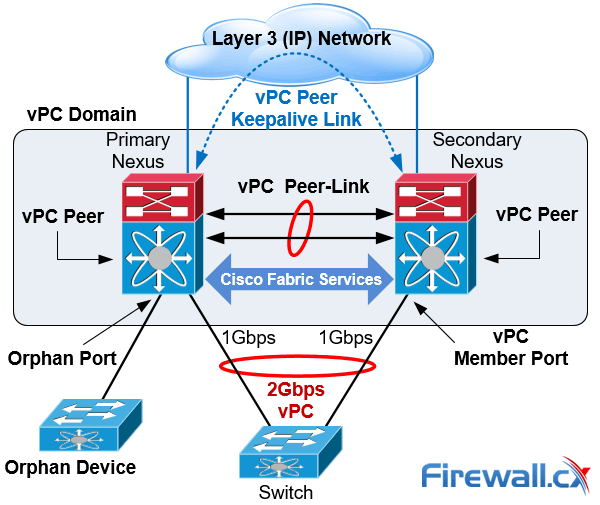
vPC Architecture Components
vPC Peer-link
The vPC peer-link is the most important connectivity element in the vPC setup. This link is used to synchronize the state between vPC peer devices via vPC control packets which creates the illusion of a single control plane. In addition the vPC peer-link provides the necessary transport for multicast, broadcast, unknown unicast traffic and for the traffic of orphaned ports. Finally, in the case of a vPC device that is also a Layer 3 switch, the peer-link carries Hot Standby Router Protocol (HSRP) packets.
vPC Peer Keepalive Link
The Peer Keepalive Link provides a Layer 3 communications path that is used as a secondary test in order to determine whether the remote peer is operating properly. In particular, it helps the vPC switch to determine whether the peer link itself has failed or whether the vPC peer is down. No data or synchronization traffic is sent over the vPC Peer Keepalive Link—only IP/UDP packets on port 3200 to indicate that the originating switch is operating and running vPC. The default timers are an interval of 1 second with a timeout of 5 seconds.
vPC Domain
This is the common domain configured across two vPC peer devices and this value identifies the vPC. A vPC domain id per device is permitted.
vPC Member Port
This is the interface that is a member of one of the vPCs configured on the vPC peers.
Cisco Fabric Services (CFS)
This protocol is used for stateful synchronization and configuration. It utilizes the peer link and does not require any configuration by the administrators. The Cisco Fabric Services over Ethernet protocol is used to perform compatibility checks in order to validate the compatibility of vPC member ports to form the channel, to synchronize the IGMP snooping status, to monitor the status of the vPC member ports, and to synchronize the Address Resolution Protocol (ARP) table.
Orphan Device
This is a device that is on a VPC VLAN but only connected to one VPC peer and not to both.
Orphan Port
An orphan port is an interface that connects to an orphan device vPC VLAN.
non-vPC VLAN
Any of the STP VLANs not carried over the peer-link.
Virtual Port Channel (vPC - Nexus) vs Virtual Switching System (VSS - Catalyst)
Virtual Switching System (VSS) is a virtualization technology that pools multiple Cisco Catalyst Switches into one virtual switch, increasing operational efficiency, boosting nonstop communications, and scaling system bandwidth capacity. VSS was first available in the Cisco 6500 series and was later introduced to the Cisco 4500, the newer 4500X, 6800 Series switches and the Catalyst 3850 (April 2017 onwards).
The vPC feature is currently not supported by any Cisco Catalyst Series Switches and is available only on the Nexus switches family.
While VSS makes use of Multi Ether Channel (MEC) to bond Cisco Catalyst Series switches together, vPC is used on Cisco Nexus Series switches for the same purpose. Both technologies are similar from the perspective of the downstream switch but there are differences, mainly in that the control plane works on the upstream devices. The next table summarizes the main characteristics and features of the VSS and vPC technologies:
|
Feature |
VSS |
vPC |
|
Multi-Chassis Port Channel |
Yes |
Yes |
|
Loop Free Topology |
Yes |
Yes |
|
Spanning Tree as failsafe protocol |
Yes |
Yes |
|
Maximum physical Nodes |
2 |
2 |
|
No Disruptive ISSU support |
No |
Yes |
|
Control Plane |
Single logical node |
Two independents active nodes |
|
Layer 3 port channel |
YES |
Limited |
|
Configuration |
Common configuration |
Two different configurations |
|
Etherchannel |
Static, PAgP, PAgP, LACP |
Static, LACP |
Table 1. Comparing Catalyst VSS with Nexus vPC
Deploying MEC or vPC could require minimal changes to an existing switching infrastructure. Catalyst Switches may need a supervisor engine upgrade to form a VSS. Then, the primary loop avoidance mechanism is provided by MEC or vPC control protocols. STP is still in operation but is running only as a failsafe mechanism. Finally, the devices e.g. access switches, servers, etc., should be connected with multiple links to Data Center Distribution or Core switches. Link Aggregation Control Protocol (LACP) is the protocol that allows for dynamic portchannel negotiation and allows up to 16 physical interfaces to become members of a single port channel.
vPC Peer Keepalive Link Design Guidelines
Taking into account the importance and impact of the Peer Keepalive link and vPC Peer-Link, Cisco recommends the following type of interconnections for the vPC Keepalive link:
|
Recommendations in order of preference for the vPC Keepalive link interconnection |
|
|
Nexus 7000 & 9000 Series Switches |
Nexus 5000 & 3000 Series Switches |
|
1. Dedicated link(s) (1GE LC) |
1. mgmt0 interface (along with management traffic) |
|
2. mgmt0 interface (along with management traffic) |
2. Dedicated link(s) (1/10GE front panel ports) |
|
3. As last resort, can be routed in-band over the L3 infrastructure |
|
Table 2. vPC Keepalive Link Interconnection methods
Special attention is needed where the mgmt interfaces of a Nexus are used to route the vPC keepalive packets via an Out of Band (OOB) Management switch. Turning off the OOB Management switch, or removing by accident the keepalive links from this switch in parallel with vPC Peer-Link failure, could lead to split brain scenario and network outage.
Using a dedicated interface for vPC keepalive link has the advantage that there’s no other network device that could affect the vPC keepalive link. Using point to point links makes it easier to control the path and minimizes the risk of failure. However, an interface for each vPC peer switch should be used to host the keepalive link. This could be a problem where there’s a limited number of available interfaces or SFPs.
Layer 3 connectivity for the Keepalive Link can be accomplished either with the SVI or with L3 (no switchport) configuration of the interfaces involved. The SVI configuration is the only option where the Nexus vPC Peer switches do not support L3 features. In any case, it is recommended to set the Keepalive Link to a separate VRF in order to isolate it from the default VRF. If the SVI is configured to route the keepalive packets, then this vlan should not be routed over vPC link. This is why the Keepalive VLAN should be removed from the trunk allowed list of the vPC Peer-Link or the vPC member ports. Allowing the Keepalive VLAN over the vPC peer trunk could lead to split brain scenario (analyzed below) and network outage if the vPC Peer-Link fails!
vPC Peer-Link Design Guidelines
The following design guidelines are recommended for the vPC Peer-Links:
- Member ports must be at least 10GE interfaces.
- Use only point-to-point without other devices between the vPC peers (Nexus switches). E.g. transceivers, microwave bridge link, etc.
- Use at least two 10Gbps links spread between two separate I/O module cards at each switch for best resiliency.
- The ports should be in dedicated mode for the oversubscribed modules.
- vPC Peer-Link ports should be located on a different I/O module than that used by the Peer Keepalive Link.
The next section describes how the vPC Nexus switches interact with events triggered by failure of links (vPC Peer Keepalive Link, Peer-Link etc) or vPC Peer switch.
vPC Failure Scenario: vPC Peer-Link Failure
In the scenario the vPC Peer-Links on the Secondary Nexus fail the status of the peer vPC is examined using the Peer Keepalive Link:
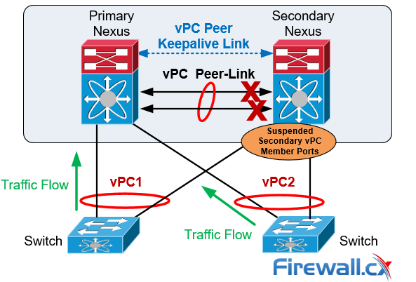
vPC Peer-Link Failure Scenario
If both vPC peers are active, the secondary vPC (i.e. the switch with the higher priority) disables all the vPC member ports to avoid uncertain traffic behavior and network loops which can result in service disruption.
At this point traffic continues flowing through the Primary vPC without any disruptions.
In the unfortunate event there is an orphan device connected to the secondary peer, then its traffic will be black-holed.
vPC Failure Scenario: vPC Peer Keepalive Link Failure
In the event the Peer Keepalive Link fails it will not have a negative effect on the operation of the vPC, which will continue forwarding traffic. The Keepalive Link is used as a secondary test mechanism to confirm the vPC peer is live in case the Peer-Link goes down:
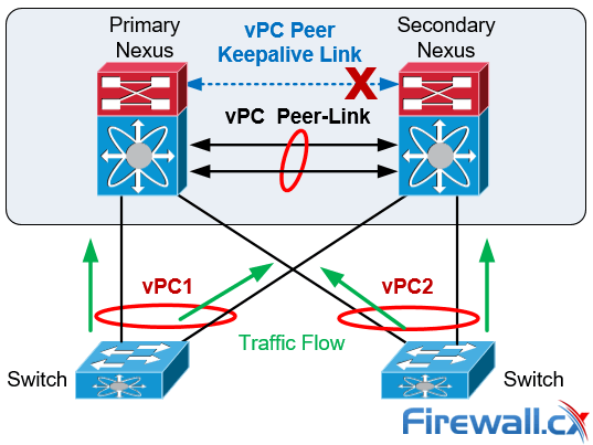
vPC Peer Keepalive Link Failure Scenario
During a Keepalive Link failure there is no change of roles between the vPC (primary/secondary) and no down time in the network.
As soon as the Keepalive Link is restored the vPC will continue to operate.
vPC Failure Scenario: vPC Peer Switch Failure
In the case of a vPC peer switch total failure, the remote switch learns from the failure via the Peer Keepalive link since no keepalive messages are received. The data traffic is forwarded by utilizing the remaining links til the failed switch recovers. It should be noticed that the Keepalive messages are used only when all the links in the Peer-Link fail:
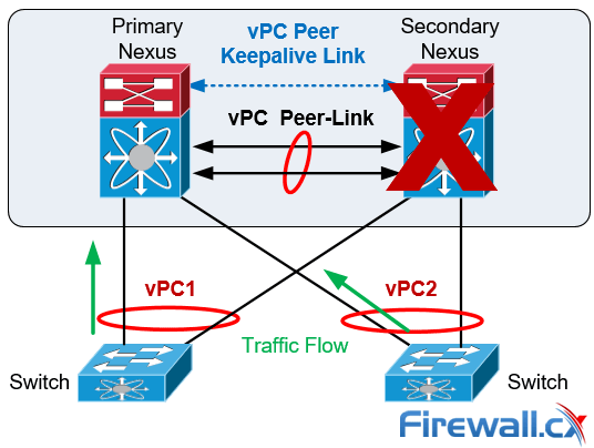
vPC Peer Switch Failure Scenario
Spanning Tree Protocol is used as a loop prevention mechanism in the case of a Peer Keepalive Link and vPC Peer-Link simultaneous failure.
vPC Failure Scenario: Dual Active or Split Brain
The Dual-Active or Split Brain vPC failure scenario occurs when the Peer Keepalive Link fails followed by the Peer-Link. Under this condition both switches undertake the vPC primary roles.
If this happens, the vPC primary switch will remain as the primary and the vPC secondary switch will become operational primary causing severe network instability and outage:
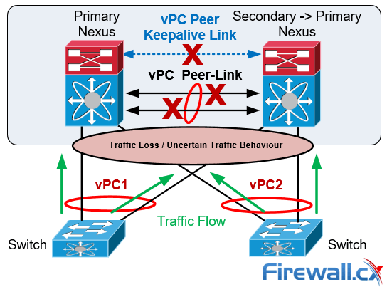
vPC Dual-Active or Split Brain Failure Scenario
Nexus vPC Configuration & Troubleshooting Guide
The vPC is configured and normal operation is verified by following the nine steps defined below. It should be noted that the order of the vPC configuration is important and that a basic vPC setup is established by using the first 4 steps:
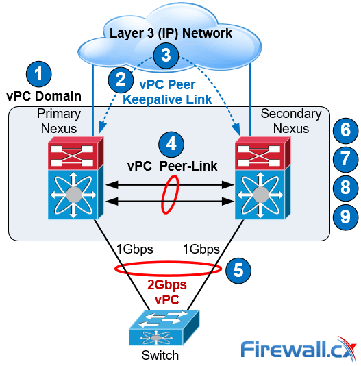
vPC Configuration Steps
Step 1: Enable the vPC feature and configure the vPC domain ID on both Nexus switches.
Step 2: Select a Peer Keepalive deployment option.
Step 3: Establish the vPC peer keepalive link.
Step 4: Configure the vPC Peer-Link.
Step 4 completes the global vPC configuration on both vPC peer switches.
Step 5: Configure individual vPCs to downstream switches or devices.
Step 6: Optionally, enable the peer gateway feature to modify the First Hop Redundancy Protocol (FHRP) operation.
Step 7: Optionally, enable the peer switch feature to optimize the STP behaviour with vPCs.
Step 8: Optionally, enable the additional features to optimize the vPCs setup.
Step 9: Optionally, verify operation of the vPC and vPC consistency parameters.
Cisco Nexus vPC Configuration Example
To help illustrate the setup of the vPC technology we used two Nexus 5548 data center switches. Typically, a similar process would be followed for any other type of Nexus switches.
Our two Nexus 5548 were given hostnames N5k-Primary & N5k-Secondary and the order outlined above was followed for the vPC setup and configuration:
Step 1: Enable the vPC Feature and Configure the vPC Domain ID on Both Switches
Following are the commands used to enable vPC and configure the vPC domain ID on the first switch:
N5k-Primary(config)# feature vpc
N5k-Primary(config)# vpc domain 1
N5k-Primary(config-vpc-domain)# show vpc role
vPC Role status
----------------------------------------------------
vPC role : none established
Dual Active Detection Status : 0
vPC system-mac : 00:23:04:ee:be:01
vPC system-priority : 32667
vPC local system-mac : 8c:60:4f:2c:b3:01
vPC local role-priority : 0
Now we configure the Nexus Secondary switch using the same commands:
N5k-Secondary(config)# feature vpc
N5k-Secondary(config)# vpc domain 1
N5k-Secondary(config-vpc-domain)# show vpc role
vPC Role status
----------------------------------------------------
vPC role : none established
Dual Active Detection Status : 0
vPC system-mac : 00:23:04:ee:be:01
vPC system-priority : 32667
vPC local system-mac : 8c:60:4f:aa:c2:3c
vPC local role-priority : 0
The same domain ID (ID 1 in our example) must be used on both vPC peer switches in the vPC domain. The output of the show vpc role command shows that the system MAC address is derived from the vPC domain ID, which is equal to 01.
Step 2: Choose a Peer Keepalive Deployment Option
Our setup below utilizes the SVI technology and the second option (dedicated 1G link) proposed for the N5k series switches keepalive link setup (table 2). This deployment option involves a dedicated VLAN with a configured SVI used for the keepalive link within an isolated VRF (named keepalive) for complete isolation from the rest of the network. Interface Ethernet 1/32 is used by both switches as a dedicated interface for the keepalive link.
On the first switch we create VLAN 23 with an SVI (assign an IP address to the VLAN interface) and make it a member of the VRF instance created for this purpose. We complete the configuration by assigning Ethernet 1/32 to VLAN 23:
N5k-Primary(config)# vlan 23
N5k-Primary(config-vlan)# name keepalive
N5k-Primary(config)# vrf context keepalive
interface Vlan23
vrf member keepalive
ip address 192.168.1.1/24
interface Ethernet1/32
switchport access vlan 23
speed 1000
duplex full
We follow the same configuration steps on our Secondary Nexus switch:
N5k-Secondary (config)# vlan 23
N5k-Secondary(config-vlan)# name keepalive
N5k-Secondary(config)# vrf context keepalive
interface Vlan23
vrf member keepalive
ip address 192.168.1.2/24
interface Ethernet1/32
switchport access vlan 23
speed 1000
duplex full
The ping connectivity test between the Peer Keepalive Links is successful:
N5k-Secondary# ping 192.168.1.1 vrf keepalive
PING 192.168.1.1 (192.168.1.1): 56 data bytes
36 bytes from 192.168.1.2: Destination Host Unreachable
Request 0 timed out
64 bytes from 192.168.1.1: icmp_seq=1 ttl=254 time=3.91 ms
64 bytes from 192.168.1.1: icmp_seq=2 ttl=254 time=3.05 ms
64 bytes from 192.168.1.1: icmp_seq=3 ttl=254 time=1.523 ms
64 bytes from 192.168.1.1: icmp_seq=4 ttl=254 time=1.501 ms
Note: The initial ICMP timeout is normal behavior as the switch needs to initially send out an ARP request to obtain 192.168.1.1’s MAC address and then send the ICMP (ping) packet.
Step 3: Establish the vPC Peer Keepalive Link
By default, the vPC Peer Keepalive packets are routed in the management VRF and use the Out-Of-Band (OOB) mgmt interface.
It is, however, highly recommended to configure the vPC Peer Keepalive link to use a separate VRF instance to ensure that the peer keepalive traffic is always carried on that link and never on the Peer-Link. In addition, the keepalive vlan should be removed from the trunk allowed list of the vPC Peer-Link or the vPC Member Ports.
N5k-Primary(config)# vpc domain 1
N5k-Primary (config-vpc-domain)# peer-keepalive destination 192.168.1.2 source 192.168.1.1 vrf keepalive
Configuration of the Secondary vPC follows:
N5k-Secondary(config)# vpc domain 1
N5k-Secondary(config-vpc-domain)# peer-keepalive destination 192.168.1.1 source 192.168.1.2 vrf keepalive
We can verify the status of the vPC Peer Keepalive Link using the show vpc peer-keepalive command on both switches:
N5k-Primary# show vpc peer-keepalive
vPC keep-alive status : peer is alive
--Peer is alive for : (95) seconds, (201) msec
--Send status : Success
--Last send at : 2017.06.22 23:03:50 720 ms
--Sent on interface : Vlan23
--Receive status : Success
--Last receive at : 2017.06.22 23:03:50 828 ms
--Received on interface : Vlan23
--Last update from peer : (0) seconds, (201) msec
vPC Keep-alive parameters
--Destination : 192.168.1.2
--Keepalive interval : 1000 msec
--Keepalive timeout : 5 seconds
--Keepalive hold timeout : 3 seconds
--Keepalive vrf : keepalive
--Keepalive udp port : 3200
--Keepalive tos : 192
Verifying the status of the vPC Peer Keepalive Link on our Secondary switch:
N5k-Secondary# show vpc peer-keepalive
vPC keep-alive status : peer is alive
--Peer is alive for : (106) seconds, (385) msec
--Send status : Success
--Last send at : 2017.06.22 22:46:32 106 ms
--Sent on interface : Vlan23
--Receive status : Success
--Last receive at : 2017.06.22 22:46:32 5 ms
--Received on interface : Vlan23
--Last update from peer : (0) seconds, (333) msec
vPC Keep-alive parameters
--Destination : 192.168.1.1
--Keepalive interval : 1000 msec
--Keepalive timeout : 5 seconds
--Keepalive hold timeout : 3 seconds
--Keepalive vrf : keepalive
--Keepalive udp port : 3200
--Keepalive tos : 192
Step 4: Configure the vPC Peer-Link
This step completes the global vPC configuration on both vPC peer switches and involves the creation of the Port-Channel to be used as the vPC Peer-Link.
First we need to enable the lacp feature then create our high-capacity port channel between the two switches to carry all necessary traffic.
The interfaces Eth1/2 and Eth1/3 are selected to become members of the vPC Peer-Link in LACP mode. In addition, the vPC is configured as a trunk. The allowed VLAN list for the trunk should be configured in such a way that only vPC VLANs (VLANs that are present on any vPCs) are allowed on the trunk. VLAN 10 has been created and allowed on the vPC Peer-Link:
N5k-Primary (config)# feature lacp
N5k-Primary(config)# interface ethernet 1/2-3
N5k-Primary(config-if-range)# description *** VPC PEER LINKS ***
N5k-Primary(config-if-range)# channel-group 23 mode active
N5k-Primary(config)# vlan 10
N5k-Primary(config)# interface port-channel 23
N5k-Primary(config-if)# description *** VPC PEER LINKS ***
N5k-Primary(config-if)# switchport mode trunk
N5k-Primary(config-if)# switchport trunk allowed vlan 10
N5k-Primary(config-if)# vpc peer-link
Please note that spanning tree port type is changed to "network" port type on vPC peer-link. This will enable spanning tree Bridge Assurance on vPC peer-link provided the STP Bridge Assurance(which is enabled by default) is not disabled.
N5k-Primary(config-if)# spanning-tree port type network
An identical configuration follows for our Secondary switch:
N5k-Secondary(config)# feature lacp
N5k-Seondary(config)# interface ethernet 1/2-3
N5k-Secondary(config-if-range)# description *** VPC PEER LINKS ***
N5k-Secondary(config-if-range)# channel-group 23 mode active
N5k-Seondary(config)# vlan 10
N5k-Secondary(config)# interface port-channel 23
N5k-Secondary(config-if)# description *** VPC PEER LINKS ***
N5k-Secondary(config-if)# switchport mode trunk
N5k-Secondary(config-if)# switchport trunk allowed vlan 10
N5k-Secondary(config-if)# vpc peer-link
Please note that spanning tree port type is changed to "network" port type on vPC peer-link. This will enable spanning tree Bridge Assurance on vPC peer-link provided the STP Bridge Assurance (which is enabled by default) is not disabled
N5k-Secondary(config-if)# spanning-tree port type network
It is not recommended to carry non-vPC VLANs on the vPC Peer-Link, because this configuration could cause severe traffic disruption for the non-vPC VLANs if the vPC Peer-Link fails. Finally, the vPC Peer Keepalive messages should not be routed over the vPC Peer-Link, which is why the VLAN associated with the Peer Keepalive connection (VLAN 23) is not allowed on the vPC Peer-Link.
We can perform a final check on our vPC using the show vpc command:
N5k-Primary# show vpc
Legend:
(*) - local vPC is down, forwarding via vPC peer-link
vPC domain id : 1
Peer status : peer adjacency formed ok
vPC keep-alive status : peer is alive
Configuration consistency status : success
Per-vlan consistency status : success
Type-2 consistency status : success
vPC role : primary
Number of vPCs configured : 0
Peer Gateway : Disabled
Dual-active excluded VLANs : -
Graceful Consistency Check : Enabled
Auto-recovery status : Enabled (timeout = 240 seconds)
vPC Peer-link status
---------------------------------------------------------------------
id Port Status Active vlans
-- ---- ------ --------------------------------------------------
1 Po23 up 10
Verifying the vPC on the Secondary peer:
N5k-Secondary# show vpc
Legend:
(*) - local vPC is down, forwarding via vPC peer-link
vPC domain id : 1
Peer status : peer adjacency formed ok
vPC keep-alive status : peer is alive
Configuration consistency status : success
Per-vlan consistency status : success
Type-2 consistency status : success
vPC role : secondary, operational primary
Number of vPCs configured : 0
Peer Gateway : Disabled
Dual-active excluded VLANs : -
Graceful Consistency Check : Enabled
Auto-recovery status : Enabled (timeout = 240 seconds)
vPC Peer-link status
---------------------------------------------------------------------
id Port Status Active vlans
-- ---- ------ --------------------------------------------------
1 Po23 up 10
The show vpc output shows that the vPC Peer-Link has been successfully established between the Nexus 5548 switches.
Step 5: Configure Individual vPCs to Downstream Devices
Individual vPCs can now be configured since the vPC domain has been properly established in the previous step.
Individual vPCs are used to connect network devices to both data center switches. For example, a router or server can connect with two or more network interfaces to both switches simultaneously for increased redundancy and bandwidth availability.
For each individual vPC, a port channel is configured on both vPC peer switches. The two port channels are then associated with each other by assigning a vPC number to the port channel interfaces:
interface Ethernet1/1
description *** Connected to ISR Gig0/2/4 ***
switchport access vlan 10
speed 1000
channel-group 10
interface port-channel10
switchport access vlan 10
vpc 10
In our setup, vpc index 10 has been assigned to port-channel 10. It is generally good practice to keep the port-channel (e.g. port-channel 10) and vpc index (e.g. vpc 10) the same to make tracking easier and avoid configuration mistakes.
Finally the vPC port number (e.g. port-channel 10) to the downstream device (e.g router) is unique for each individual vPC within the vPC domain and must be identical between the two peer switches as shown in the diagram below:
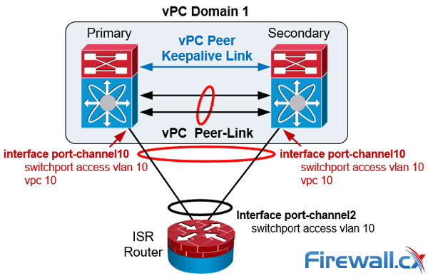
Nexus vPC port-channel configuration to downstream devices
Finally the vPC member ports should have a compatible and consistent configuration for all the ports to both switches. Here is the configuration on the Primary Nexus switch:
interface Ethernet1/1
description *** Connected to ISR Gig0/2/0 ***
switchport access vlan 10
speed 1000
channel-group 10
interface port-channel10
switchport access vlan 10
vpc 10
Verifiying our vPC to the downstream device from the Primary vPC:
N5k-Primary# show vpc | begin "vPC status"
vPC status
----------------------------------------------------------------------------
id Port Status Consistency Reason Active vlans
------ ----------- ------ ----------- -------------------------- -----------
10 Po10 up success success 10
Verifiying our vPC to the downstream device from the Secondary vPC:
N5k-Secondary# show vpc | begin "vPC status"
vPC status
----------------------------------------------------------------------------
id Port Status Consistency Reason Active vlans
------ ----------- ------ ----------- -------------------------- -----------
10 Po10 up success success 10
Step 6: (Optional) Enable the Peer-Gateway Feature to Modify the FHRP Operation
The vPC Peer-Gateway feature causes a vPC peer to act as a gateway for packets that are destined for the peer device’s MAC address. So, it enables local forwarding of such packets without the need to cross the vPC Peer-Link. This feature optimizes the use of the peer link and avoids potential traffic loss in FHRP scenarios.
When enabled, the peer gateway feature must be configured on both primary and secondary vPC peers:
N5k-Primary(config)# vpc domain 1
N5k-Primary(config-vpc-domain)# peer-gateway
Configuring the secondary vPC peer:
N5k-Secondary(config)# vpc domain 1
N5k-Secondary(config-vpc-domain)# peer-gateway
Step 7: (Optional) Enable the Peer-Switch Feature to Optimize the STP Behaviour with the vPCs
This feature allows a pair of Cisco Nexus switches to appear as a single spanning tree root in the Layer 2 topology. It eliminates the need to pin the spanning tree root to the vPC primary switch and improves vPC convergence if the vPC primary switch fails:
N5k-Primary(config)# vpc domain 1
N5k-Primary(config-vpc-domain)# peer-switch
Configuring the peer-switch command on the Secondary vPC:
N5k-Secondary(config)# vpc domain 1
N5k-Secondary(config-vpc-domain)# peer-switch
Step 8: (Optional) Optimize vPC performance: ‘ip arp synchronize’, ‘delay restore’, ‘auto-recovery’, ‘graceful consistency-check’ & ‘role priority’ commands
Configure the following vPC commands in the vPC domain configuration mode, this will increase resiliency, optimize performance, and reduce disruptions in vPC operations.
The ip arp synchronize feature allows the synchronization of the ARP table when the peer-link comes up. The vPC offers the option to delay the restoration of the vPC ports for a configurable time by using the delay restore command, which is useful to avoid traffic blackholing after a reboot of the switch. The auto-recovery command has a default timer of 240 seconds.
In addition, it is recommended to use the configuration synchronization graceful consistency-check feature to minimize disruption when a Type 1 mismatch occurs. Examples of Type 1 mismatches could be the STP mode or the STP port type between the vPC peer switches. The show vpc consistency-parameters global output illustrates the Type 1 and Type 2 parameters of a vPC.
The commands below enable and configure all the above mentioned features:
N5k-Primary(config)# vpc domain 1
N5k-Primary(config-vpc-domain)# delay restore 360
N5k-Primary(config-vpc-domain)# auto-recovery
Warning:
Enables restoring of vPCs in a peer-detached state after reload, will wait for 240 seconds to determine if peer is un-reachable
N5k-Primary(config-vpc-domain)# graceful consistency-check
N5k-Primary(config-vpc-domain)# ip arp synchronize
Once the Primary switch is configured we apply the same configuration to the Secondary switch:
N5k-Secondary(config)# vpc domain 1
N5k-Secondary(config-vpc-domain)# delay restore 360
N5k-Secondary(config-vpc-domain)# auto-recovery
Warning:
Enables restoring of vPCs in a peer-detached state after reload, will wait for 240 seconds to determine if peer is un-reachable
N5k-Secondary(config-vpc-domain)# graceful consistency-check
N5k-Secondary(config-vpc-domain)# ip arp synchronize
Finally, it should be noted that it is feasible to set the role priority under vpc domain configuration with the command role priority to affect the election of the primary vPC switch.
The default role priority value is 32,667 and the switch with lowest priority is elected as the vPC primary switch.
If the vPC primary switch is alive and the vPC Peer-Link goes down, the vPC secondary switch suspends its vPC member ports to prevent dual active scenario, while the vPC primary switch keeps all of its vPC member ports active. It is recommended for this reason the orphan ports (ports connecting to only one switch) be connected to the vPC primary switch.
Verifying Operation and Troubleshooting the Status of the vPC
The show vpc brief command displays the vPC domain ID, the Peer-Link status, the Keepalive message status, whether the configuration consistency is successful, and whether a peer link has formed. It also states the status of the vPC Port Channel (Po10 in our setup).
N5k-Primary# show vpc brief
Legend:
(*) - local vPC is down, forwarding via vPC peer-link
vPC domain id : 1
Peer status : peer adjacency formed ok
vPC keep-alive status : peer is alive
Configuration consistency status : success
Per-vlan consistency status : success
Type-2 consistency status : success
vPC role : primary, operational secondary
Number of vPCs configured : 1
Peer Gateway : Enabled
Peer gateway excluded VLANs : -
Dual-active excluded VLANs : -
Graceful Consistency Check : Enabled
Auto-recovery status : Enabled (timeout = 240 seconds)
vPC Peer-link status
---------------------------------------------------------------------
id Port Status Active vlans
-- ---- ------ --------------------------------------------------
1 Po23 up 10
vPC status
----------------------------------------------------------------------------
id Port Status Consistency Reason Active vlans
------ ----------- ------ ----------- -------------------------- -----------
10 Po10 up success success 10
The show vpc consistency-parameters command is useful for troubleshooting and identifying specific parameters that might have caused the consistency check to fail either on the vPC Peer-Link or to the vPC enabled Portchannels:
N5k-Primary# show vpc consistency-parameters global
Legend:
Type 1 : vPC will be suspended in case of mismatch
Name Type Local Value Peer Value
------------- ---- ---------------------- -----------------------
QoS 2 ([ ], [ ], [ ], [ ], [ ], ([ ], [ ], [ ], [ ], [ ],
[ ]) [ ])
Network QoS (MTU) 2 (1538, 0, 0, 0, 0, 0) (1538, 0, 0, 0, 0, 0)
Network Qos (Pause) 2 (F, F, F, F, F, F) (F, F, F, F, F, F)
Input Queuing (Bandwidth) 2 (100, 0, 0, 0, 0, 0) (100, 0, 0, 0, 0, 0)
Input Queuing (Absolute 2 (F, F, F, F, F, F) (F, F, F, F, F, F)
Priority)
Output Queuing (Bandwidth) 2 (100, 0, 0, 0, 0, 0) (100, 0, 0, 0, 0, 0)
Output Queuing (Absolute 2 (F, F, F, F, F, F) (F, F, F, F, F, F)
Priority)
STP Mode 1 Rapid-PVST Rapid-PVST
STP Disabled 1 None None
STP MST Region Name 1 "" ""
STP MST Region Revision 1 0 0
STP MST Region Instance to 1
VLAN Mapping
STP Loopguard 1 Disabled Disabled
STP Bridge Assurance 1 Enabled Enabled
STP Port Type, Edge 1 Normal, Disabled, Normal, Disabled,
BPDUFilter, Edge BPDUGuard Disabled Disabled
STP MST Simulate PVST 1 Enabled Enabled
IGMP Snooping Group-Limit 2 4000 4000
Interface-vlan admin up 2 10 10
Interface-vlan routing 2 10 10
capability
Allowed VLANs - 10 10
Local suspended VLANs - - -
N5k-Primary# show vpc consistency-parameters vpc 10
Legend:
Type 1 : vPC will be suspended in case of mismatch
Name Type Local Value Peer Value
------------- ---- ---------------------- -----------------------
Shut Lan 1 No No
STP Port Type 1 Default Default
STP Port Guard 1 None None
STP MST Simulate PVST 1 Default Default
mode 1 on on
Speed 1 1000 Mb/s 1000 Mb/s
Duplex 1 full full
Port Mode 1 access access
MTU 1 1500 1500
Admin port mode 1 access access
vPC card type 1 Empty Empty
Allowed VLANs - 10 10
Local suspended VLANs - - -
vPC Quiz
Our Nexus 5500 switches used the management interface to establish the vPC keepalive link between them. The management interfaces on both switches are connected to a 2960 Catalyst management switch which was accidently switched off due to an unplanned power disruption, causing the management interface and vPC keepalive link to go down. What is the impact of this failure on the Nexus vPC setup?
Answer:
There will be no service impact to the Nexus infrastructure! Read the vPC failure scenarios section in this article for a thorough explanation.
Summary
In this article we reviewed the Nexus vPC features and vPC design guidelines. In addition we discussed the vPC architecture components and explained the importance of each component.
Next we analyzed different vPC failure scenarios including vPC Peer-Link Failure and Peer Keepalive link failure. We compared vPC with VSS technology developed for the Catalyst Switches in order to provide MEC feature capabilities. Finally, the vPC configuration guide and best practices section showed how to configure vPC and apply optional configuration commands to increase resiliency and reduce disruptions in vPC operations. We also provided useful show commands needed to validate and troubleshoot the status of the vPC.
Your IP address:
18.188.187.146
Wi-Fi Key Generator
Follow Firewall.cx
Cisco Password Crack
Decrypt Cisco Type-7 Passwords on the fly!


